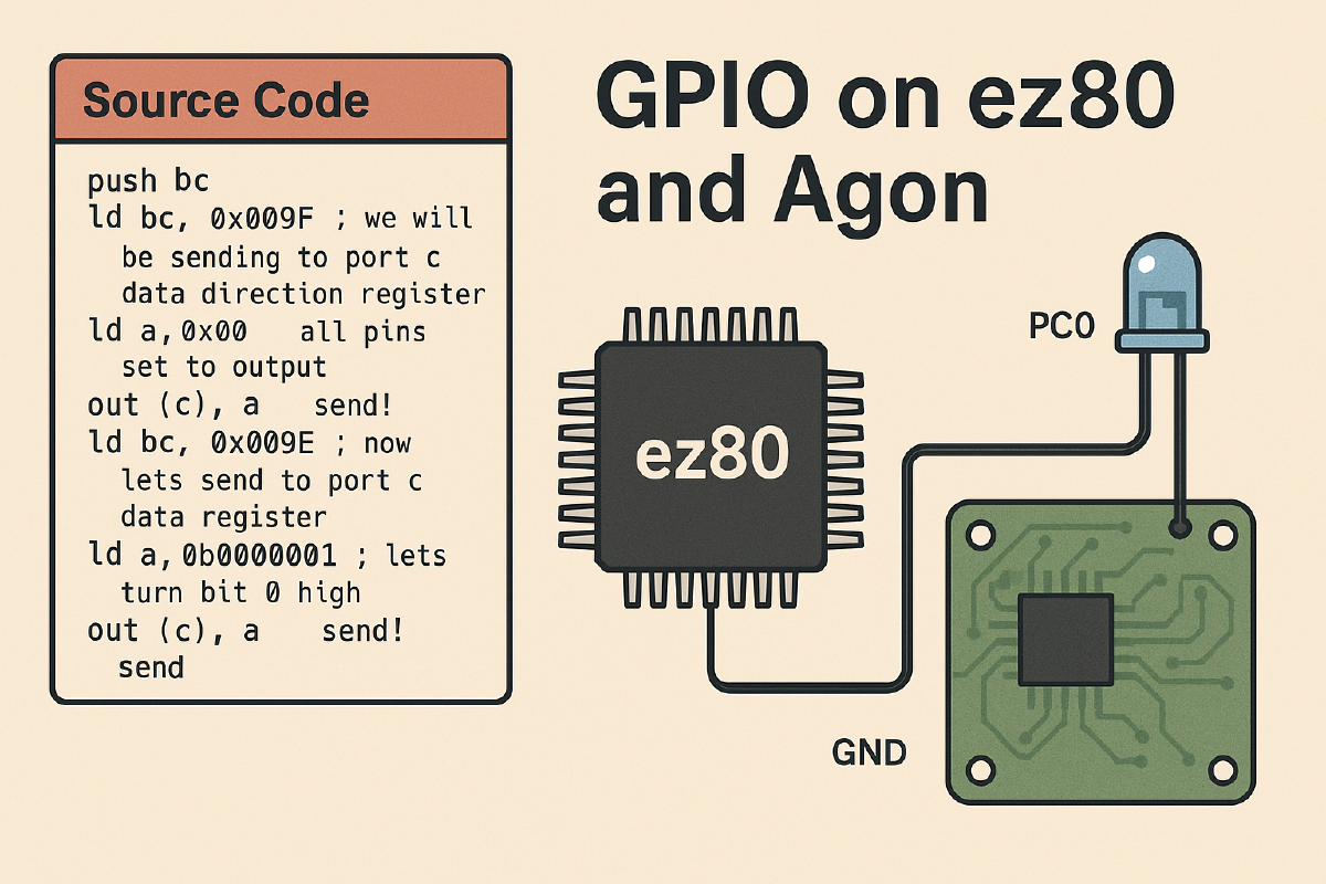
Source code#
If you are only interested in source code here it is!
Preface#
While looking through Agon documentation and materials I stumbled upon examples of using GPIO with Basic, but I never saw any examples on how to use it from C or Assembly - so here it is!
Agon exposes multiple GPIO pins from ez80 MPU and esp32 VDP - we will be covering only ez80 part today. Before connecting anything to your agon please look here. Connectors on each of Agon versions slightly differ from each other.
IN and OUT!#
If you are familiar with 6502 cpu then you might be a bit surprised but ez80 does not communicate with external devices via main memory. It have separate addressing and assembly commands to work with external devices(registers):
So basically if you want to output something to a device - you need to put its address into bc register and value into one of 8 bit registers, a for example.
push bc
ld bc, 0x009F
ld a, 0xA0
out (c), a
pop bc
Above code will output 0xA0 into device at address 0x009F.
WARNING!!!! Please be aware that
out (c), ais the most misleading command in entire z80 world ;) It will takebceven you are not specifyingbcin the command itself!
Similarly if you want to read some data from device:
push bc
ld bc, 0x009F
in a, (c)
WARNING!!!! Same situation as with output!
Now you should have value from 0x009F in a register.
GPIO on ez80#
Now you know how to send and receive data from devices - but you don’t know yet where to send it. You can ofcourse find it in hardware specification - or you can read this post further :)
ez80 MCU contain 24 general-purpose Input/Output pins. These pins are assembled as three 8-bit ports: B, C and D. All of these ports can be used as inputs or outputs, in more advanced usecase - you can use those as interrupt sources (not covered here).
Each of GPIO ports is controlled via 4 external registers:
- Px_DR: Data register
- Px_DDR: Data direction register
- Px_ALT1: Alternate register 1
- Px_ALT2: Alternate register 2
and can work in 7 different modes of operation. In this guide we will only tackle Mode 1(digital output) and Mode 2(digital input). Mode 1 and Mode 2 can be used without touching PxALT1 and PxALT2 registers - as these are preset for these modes at MPU start.
To configure pin as output you just need to set correct Px_DDR pin to 0, and to configure as input you need it set as 1.
In below table you can find external register addresses for GPIOs:
| Port | DR | DDR | ALT1 | ALT2 |
|---|---|---|---|---|
| B | 0x009A | 0x009B | 0x009C | 0x009D |
| C | 0x009E | 0x009F | 0x00A0 | 0x00A1 |
| D | 0x00A2 | 0x00A3 | 0x00A4 | 0x00A5 |
GPIO on Agon#
As mentioned in the beginning - you can find Agon pinouts here.
Now lets do a simple example of setting GPIO port as output and setting its value to high.
We will assume that something is connected to Agon PC0 pin. PC0 means Port C, bit 0.
push bc
ld bc, 0x009F ; we will be sending to port c data direction register
ld a, 0x00  ; all pins set to output
out (c), a  ; send!
ld bc, 0x009E ; now lets send to port c data register
ld a, 0b00000001 ; lets turn bit 0 high
out (c), a  ; send!
If you connect LED diode + into PC0 and LED diode - into GND it should be switched on now!
Similarly you can take input by configuring pins as input and executing in command on DR port.
That’s it! You know how to use GPIO ports on Agon now. You can also find example on how to use GPIO ports from C here
